Friction bolts in IDEA StatiCa
A little dive into how friction bolts work in real life and in IDEA StatiCa
Stress distribution and redistribution
Post-slip stage of friction bolts and how to calculate it in IDEA StatiCa
Slotted holes work
I’ve tried not to write too much, because there are too many topics that can be discussed, so let this post be just a small run-through about this and that.
There are two main ways of transfer of shear force though a bolted connection:
Bolts in shear / plates in bearing
Friction connection
For each group of bolts in IDEA StatiCa you can choose how these bolts will transfer shear force:
I don’t want to devote too much time to compare the models of bolt components.
Maybe a little bit later I could try to write an additional post about these models. By the way, you are always welcome to let me know if you are interested!
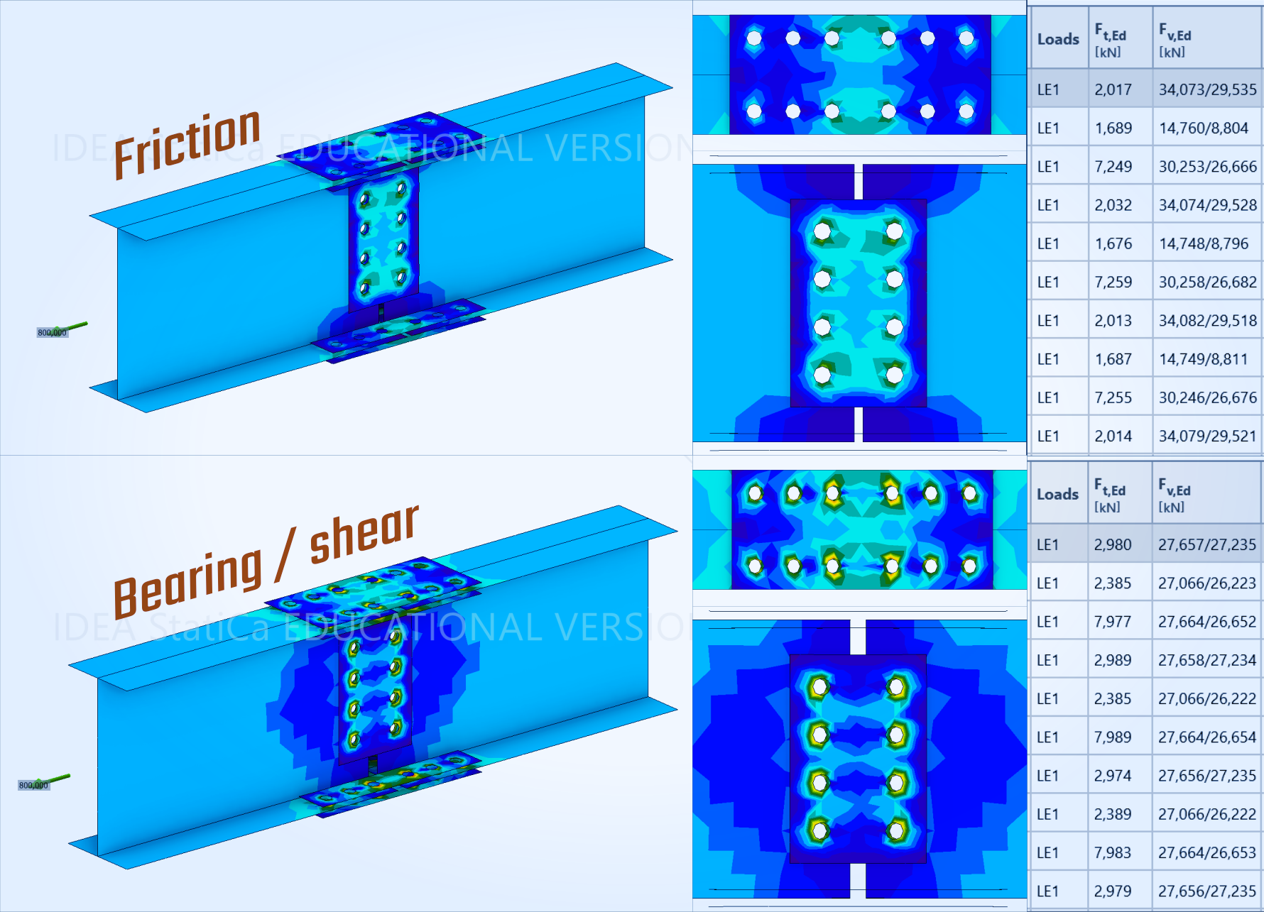
The main thought here is that the results depend on bolt model. Not only code-check results, but the stress-displacements picture and distribution of forces in bolts also.
Bolts in IDEA StatiCa are represented by special “springs” with certain stiffness. These springs stiffnesses are calculated and calibrated according to codes and experiments and their magnitude is affected by the bolt diameter, grade and other factors. And, certainly, the stiffness calculation for bearing and friction bolts is not the same. Component method in Eurocode 1993-1-8 gives a finite number of stiffness of the component for bearing bolts and literally infinite for friction (6.3.2).
So the friction bolt model has much more stiffness and thus the effects of uneven stresses distribution appear more clearly on them.
Picture looks familiar if you have read the post about stress distribution in welds, right? If not, click the button to read!
Is it plastic redistribution again?
No, not the plasticity here, but the process is quiet similar.
Let's remember school physics. How the frictional force works in general case?
For the body sitting on a surface without any external action the friction force is zero.
When something tries to move the body, the frictional force resists to movement with the force same in magnitude.
It is static friction.The limit of frictional force is μ∙N. After external force achieves this value, the body moves. But frictional force remains with this limit value, it doesn’t disappear.
F_fric ≤ μ∙N
So the principle is pretty easy for any friction connections, and friction bolts as just a special case of friction connections work the same way.
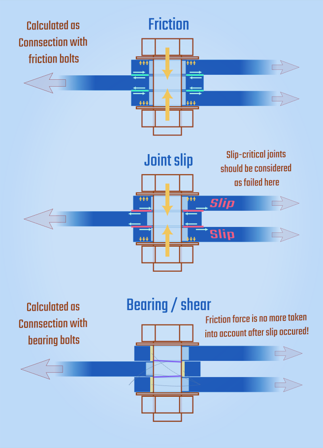
When surfaces around one bolt achieving the frictional force limit, small slip appears, but the frictional force of this particular bolt connection remains the same.
These small slippage effects let all the bolts in a group to act together when the global slip occurs.
If you want to read more, I would love to recommend the “Guide to Design Criteria for Bolted and Riveted Joints” by Geoffrey L. Kulak, John W. Fisher, John H. A. Struik. This particular effect is described in chapter 5.2, but the whole book is a comprehensive guide friction bolts principles and design recommendations with informative description of experiments that underlie many of the design codes.
What happens when all the bolts slip?
This depends on the design code you use :)
It is usual to consider that after the joint slip occurs bolts just move to shear-bearing type. For example, this is applied to in EC 1993-1-8 c. 3.4.1 for Category B bolts. Furthermore, AISC / RCSC directly requires to check the bolts for shear/bearing stage in all the slip-critical joints.
It is not recommended to consider friction and bearing together at the post-slip stage — the calculation should include either friction or bearing. So usually engineer calculates the connection for frictional forces in normal design situation and for bearing forces, if needed, for post-critical situation.
In IDEA StatiCa friction bolts do not change their model from friction to bearing automatically. You need to calculate two separate problems.
As example, in case of Eurocode Category B connection, with friction bolts for serviceability loads and with bearing bolts for ultimate loads.
Don’t forget that the requirements for distances (edge or between) may be different in your design code, so if you choosing to calculate joint for both stages, joint should meet both the requirements.
Slotted holes
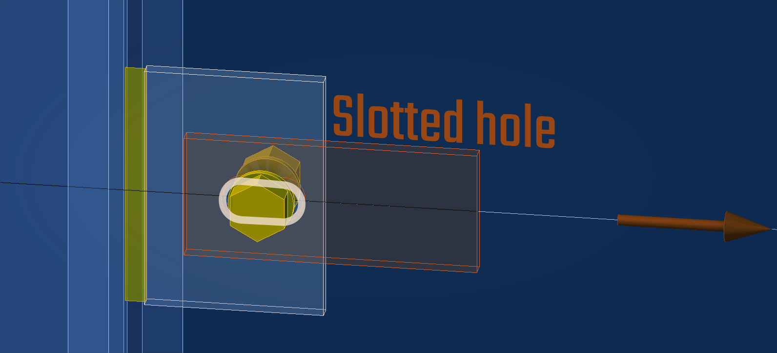
One simple additional difference between bearing and friction bolts models is how they work in slotted holes.
For a bearing bolt a slotted hole is a degree of freedom in the certain direction. Friction bolt doesn’t interact directly with the hole edge, so more or less nothing changes in its working principle.
Of course, for such slotted-hole connections post-slip stage is impossible in general case — they should be calculated only as slip-critical.
If such a joint being designed according to Eurocode, IDEA StatiCa will automatically use factors from table 3.6 of EN 1993-1-8, but if you design the joint according to AISC, you need to manually set the factor φ or Ω in the code setup menu.
Code setup
The Code Setup window looks different for different design codes.
Here I want to compare how the setup affect on the difference between Eurocode and AISC codes.
Different friction surface processing techniques lead to different friction factor μ, so this factor influences on the check result directly and proportionally and it is important to set it in Code Setup menu.
The exact value of this factor depends on code and usually varies from around numbers 0.3 to 0.6.
Additionally, the code setup for friction bolts may include:
pretension force factor (which is usually equal 0,7 in most of codes)
load type for friction connections for SP code. For SP you can also set an optional factor based on number of bolts in a connection or leave it for the program to decide
slotted / oversized joint factor for AISC code as shown below
Conclusion
I hope that this overview helped you to get an idea of:
how the friction bolted connections work in IDEA StatiCa,
how forces distribution and redistribution works for bolts,
how to model them and how to set up their properties,
how to model post-slip work of friction bolts if it is needed,
how the shape of the bolt hole affects on the friction bolted connection.
Please feel free to give a feedback if it was helpful, here in comments or in social media. And if you believe that I’ve made a mistake somewhere, your feedback will be doubly welcomed!
STILL HAVE QUESTIONS?
The connections acts a significant role in structural design. When to use friction bolts? How to model them properly in a certain case? How do I make my own verification or a test model? How to read the report results?
If you have any additional questions or want to deepen your knowledge, consider joining one of our comprehensive IDEA StatiCa courses.
Explore our courses to find the one that suits your needs best or request a custom course.
Get in touch with us today to learn more or to sign up!


