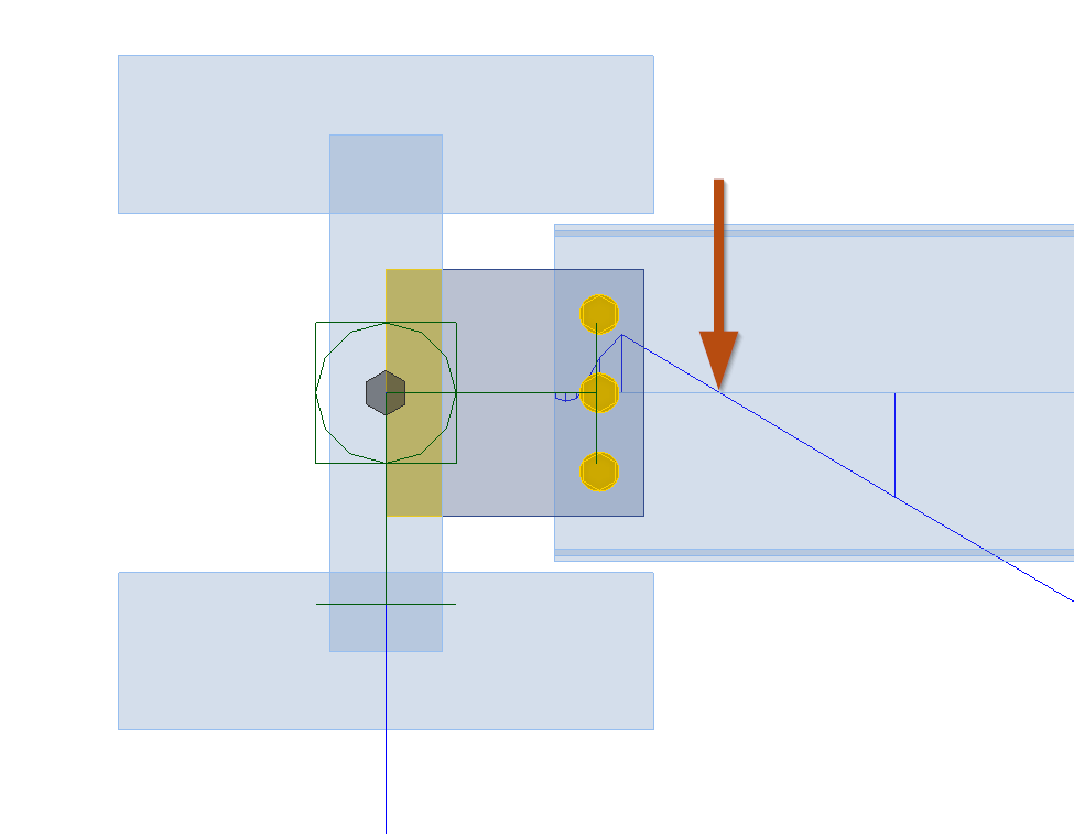
Position of hinge
Sometimes the positioning of the hinge can be tricky. In this post I’ll try to explain the most important and unobvious aspects of this topic.
“What is the position of the hinge?”
“How can we know where exactly to set it?”
“How does it affect the results?”
“Are there any universal answers?”
And, finally: “Why does my beam lifts up in IDEAStatiCa?!”’
If you've ever wondered how to correctly place force application points in nodes in IDEA StatiCa, this guide is for you. We'll break it down step by step and make it easy to understand.
Let’s start from the experiment.
Experiment 1
Let’s study this simple fin-plate connection between two simple I-beams. Assume that we have no concrete slab or anything stiff enough to constrain our beams.
On the right panel we can find the drop-down option named as “Forces in”.
Let’s see what happens when we choosing options “Bolts” and “Node”.
1. Option “Bolts”
Everything looks… normally?
Or not?
Look at column F.v.Ed.
Here we can see the shear forces on bolts. And they are quite equal. Do we really expect it here?
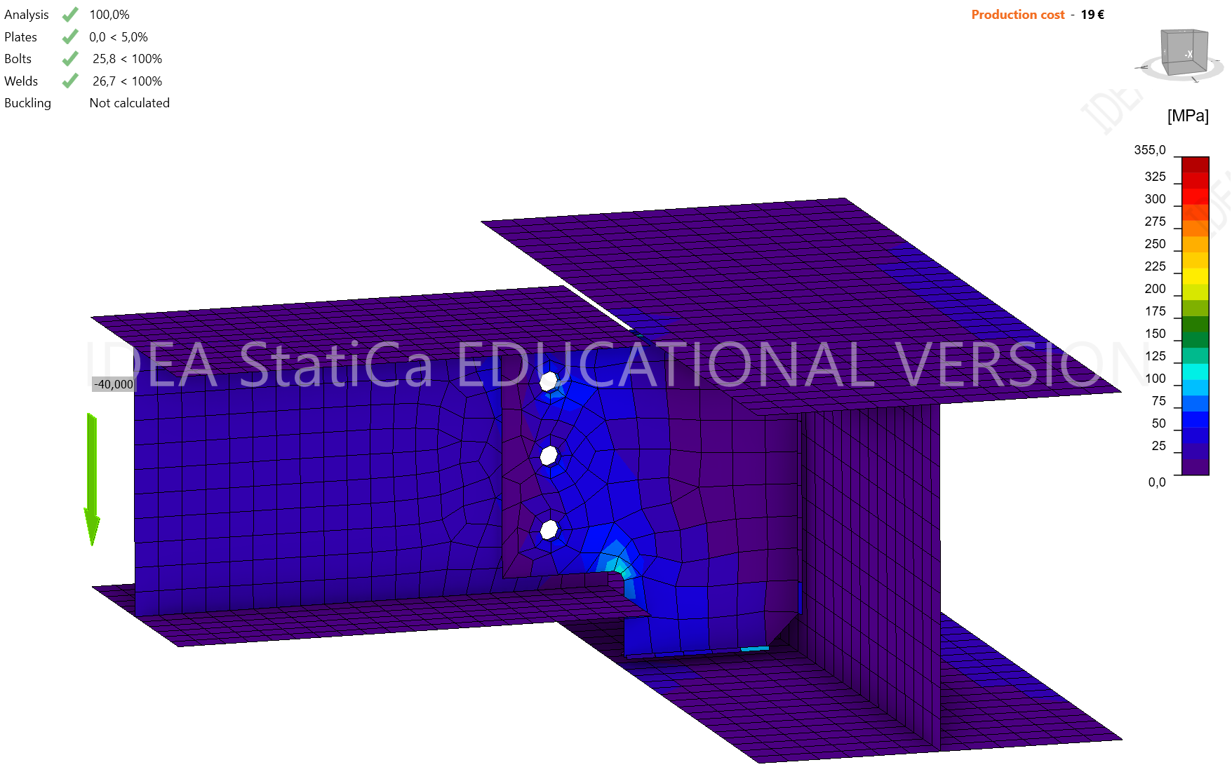
2. Option “Node”
Oh, here the beam lifts up! Program error, right?
Or not?
Bolts shear forces in the F.v.Ed
Bolt forces are much greater!
At least we can see now, that position of the hinge can significantly affect the results.
What is “position of the hinge”?
We saying “position of the hinge” since we are considering the pinned connection. But what is the hinge? All the joint is a hinge, isnt’t it?
From the perspective of the global structural model, everything is pretty simple — hinge is on the very end of the beam. But since we looking at the joint closely, we need to be precise for details.
So we need to find the point on beam axis, where we expecting the moment to be equal to zero. For fin-plated connection it is usually bolts, especially when a beam connects to quite rigid column.
Look at pictures below:
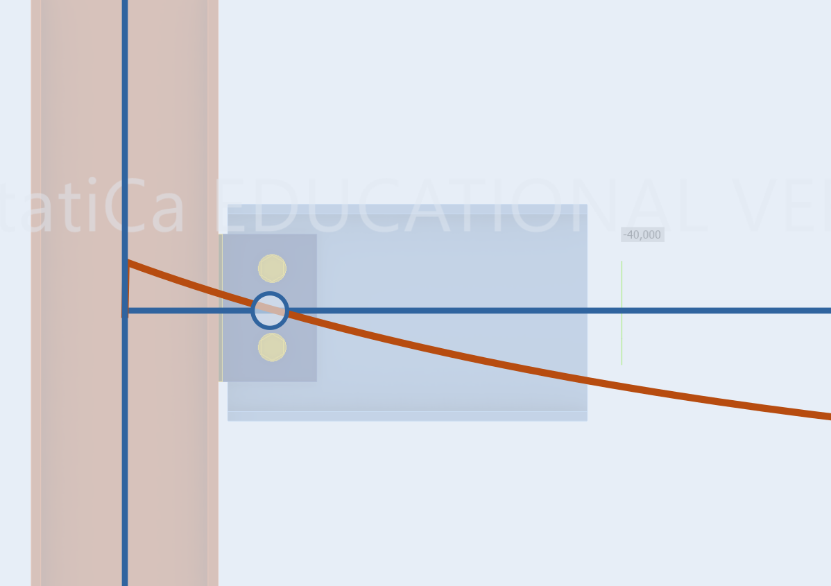
This is the beam how we see it in stick FEM model. The hinge is on the very end and the zero-moment point is there. Moreover, in the global calculation zero-moment point is there because we applied there the hinge.
But in real structures it is usual that the hinge can move a little from that point. In global model we don’t bother, but since we looking on our joint closely, we need to consider such things.
This occurs usually (but not always, we will talk about it further) because of the eccentricity of bolts from the “central point” of the node.
This is example of when hinge is situated outside of intersection of centerlines of beam and column.
In such case you should usually choose the “bolts” position of applying forces.
Should I always use “bolts” option for such connections?
No, not always.
Look at the very first experiment that we tried to perform. Do you remember that we assumed nothing rigid on the top of our beams, so nothing interferes the main beam from torsion, right?
Which assumption works better here?
Is there any torsional rigidity in main beam to resist the torsion?
No, the main beam has an open section which means that it has very poor torsional stiffness.
But if there are no rigidity in the main beam, and no rigidity in bolts.. then we have two hinges, is it going to fail?
No, let’s see how bolts work here.
At first, this is bending moment.
Just multiply the shear force on eccentricity and you’ll get the moment on bolts.
And now, divide result to this distance between bolts (h) and get the horizontal force on bolt (if you have more than 3 bolts it is little harder, but the principle is the same).
So here we are, bolts work not only for vertical force, but for horizontal also.
IDEA StatiCa gives nice illustration of all that we discussed above.
Just switch to the transparent view:
“Forces in: Node”
“Forces in: Bolts”
Please, always check these diagrams to be sure that you set everything right.
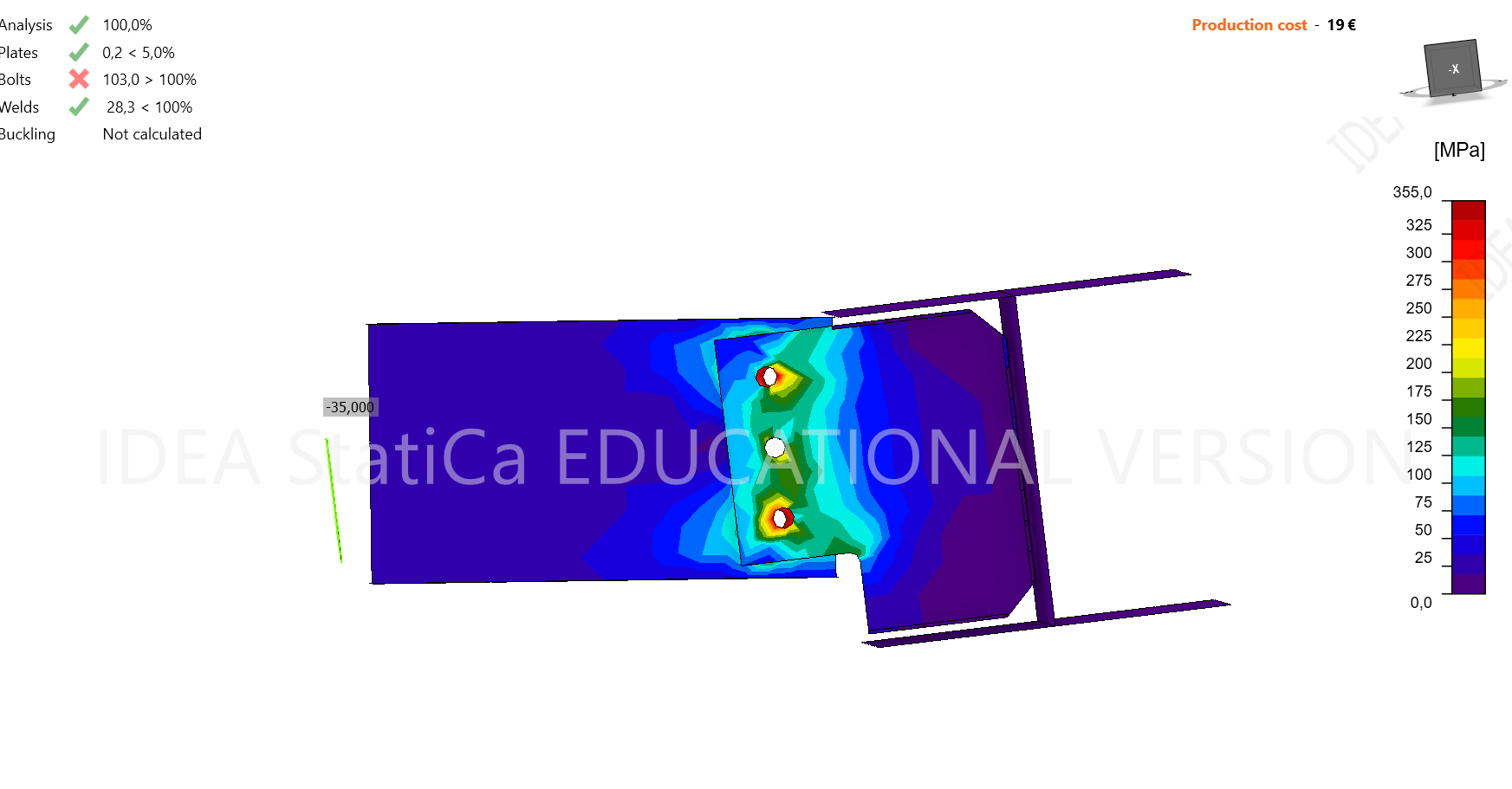
And familiar picture of bolt forces in results.
Top and bottom bolts are loaded mostly with horizontal force and that is why they are “red" — because of additional forces.
So why is the secondary beam lifts up if the “Node” option is the right one for our problem?
The answer is that everything is relative. Just skew your head a little and you will see, that picture corresponds to our expectations! The main beam rotated a little in fact.
But this is how forces are applied in IDEA StatiCa to beams. They are not applied to bolts. They are not applied to any particular point inside the joint. They are applied to the “free” edge of the element. And free edge gets its bending moment and shear force. Yes, moment. Because if your beam has non-zero shear force, so moment will vary. And if we want moment in any particular point to be zero, than we need not to forget that in all other point it will not be zero.
And that is why we can say that no errors occurred here in fact.
How can I know the exact position of the hinge?
As I demonstrated to you above, even bolts in pin-connection can bear some moment. And in fact connections are not divided to rigid ones and pinned ones. No. Connections rigidity can vary in a wide spectrum of values.
So for some cases we have the firm rules. If such fin-plated pinned connection connects the beam to stiff column, you can bravely assume hinge in bolts. Beam-to-beam connection (if the main beam is not really huge and if there are no constraints that prevents its rotation) usually assumed with hinges in the center of main beam.
But there are sometimes not so obvious cases.
There are three possible ways.
Most conservative — calculate the connection this way and another to be sure that connection resists any moment diagram. This approach cannot be justified in most cases and I would NOT recommend it in most of cases.
Member.
Engineering judgement. I would recommend you this way, but only if you are sure with your assumptions. Otherwise — please try to practice with some problems with 2nd approach — with Member.
Member? What member?
I mean IDEA StatiCa Member. You can model the secondary beam with its real rigidity and with real rigidity of the main beam and with other details. And you will see the real moment diagram and it will show you the point of hinge — the zero-moment point.
Experiment 2. How to find the zero-moment point in IDEA StatiCa Member
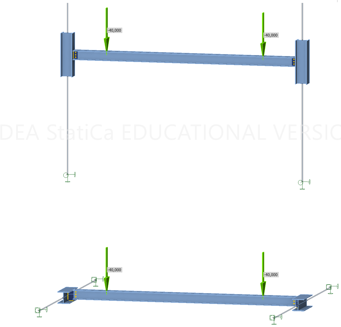
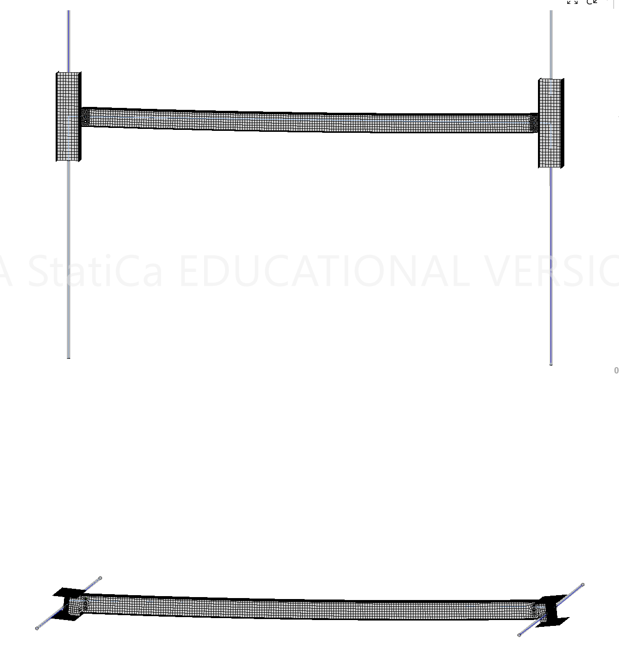
Disposition of our experiment.
Case one: beam is supported by two quite rigid columns from their “strong” direction. So here we expect to find the hinge in bolts or very close to them.
Case two: beam is supported by two beams, the same as in Experiment 1, with exactly the same connection.
PS: Yes, I made both cases in one model and they are independent. It is possible in Member.
Deformations
As we expected, the supporting beams rotate and they are stopped by bolts in the connection.
In the meantime it looks like columns on the upper structure haven’t even noticed the load.
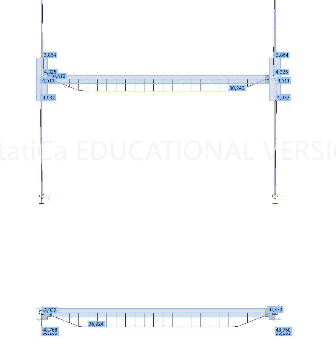
Moment diagrams!
That is the reason of why we calculate this.
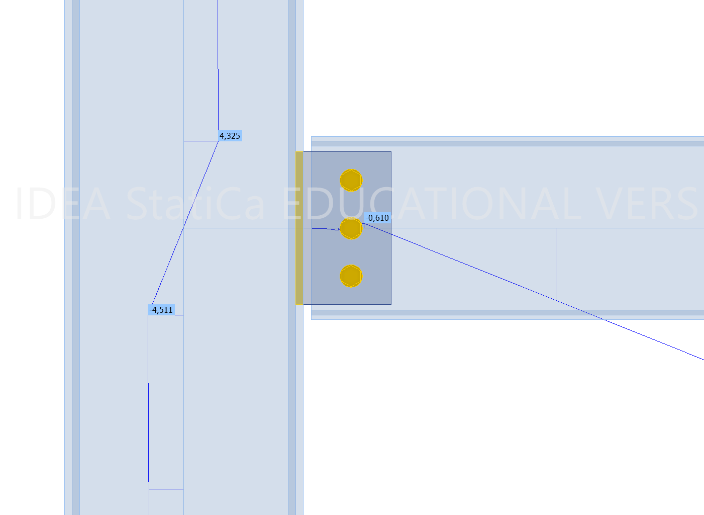
Let's take a closer look.
The zero-moment point is really close to the bolts!
Yes!
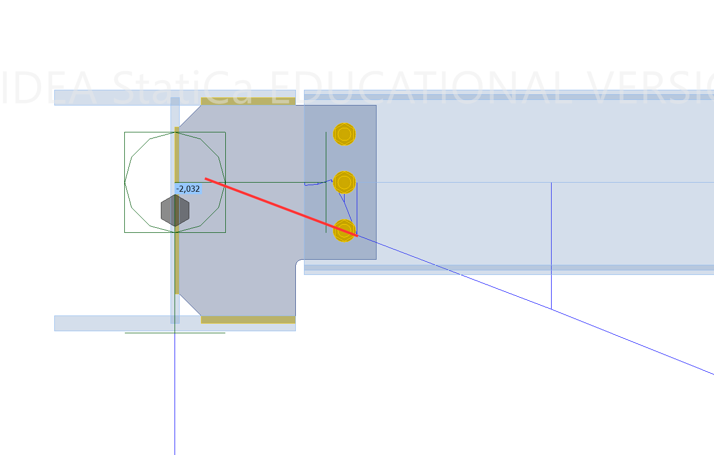
The zero-moment point is inside the main beam. Not exactly in the the center of it, but for this case to assume it to be in “Node” is the reasonable reserve.
So, I should check every connection in member?
No, please, don’t do it every time. This is just a test to demonstrate assumptions and approve approaches.
But yes, it can be useful and quite universal technic when you are not sure enough.
“Forces in: Position”
This is simple.
Node = position 0.
Position of 100 mm is… 100 mm away from position = 0 along the beam axis :)
There exist one tricky thing, that when you applying “Offset ex” to your secondary beam, the “Position = 0” point will also move. It is not obvious, so please, always check the moment diagram.
“Forces in: connected member face”
This option’s name speaks for itself. The point where secondary member’s axis meets the main member’s surface.
How about Rigid moment connections?
For rigid connections there is no need to search the zero-moment point. Just be always sure that the point for “forces in:“ corresponding to the position, wherefrom you took the results in your stick-model. Usually it is just the Node point.
… and exotic cases
Let’s determine positions for something more complicated.
What if secondary members are inclined and / or passing by the “Node point”, like on the pictures below? How to find their points those correspond to “Position = 0”?
It is easy. Just build a perpendicular from the Node point to the beam axis and this would be the Position = 0 point for that beam.
What else do I need to know?
As we mentioned before — stiffness can vary. Your connection will always have some amount of stiffness. And your main and secondary elements will always have some non-infinite stiffness. And all these stiffnesses will affect on the moment diagram for your beam.
Try to always train you engineering judgment, your intuition. And when you feel that your beam is too firm or slender or connection is not typical — you can always make a double check with Member.
I want to demonstrate an example of how rigidity of the beam affects the moment diagram and therefore the position of zero-moment point.
Experiment 3
Sections of secondary beam are the same.
All the connections are equal with the same eccentricity.
Supporting members have the same length but different section and therefore different rotational stiffness.
As we mentioned in the Experiment 1, usually, if the supporting beam have an open section (like I-beam, channel etc.) it is normal to assume that the zero-moment point will stay on its axis or near it.
But sometimes the main beam is too big. Let’s have a look at the results.
Main beam has the same section as the secondary
Hinge is situated perfectly in the center of the supporting beam!
Main beam has the way bigger section than the secondary
Now hinge is closer to the bolts but the assuming of the hinge point in the center of main beam will not be too conservative here. But it’s up to you, of course.
Main beam is still an “open section”, but it is now a leviathan among I-sections — HD 400x1299.
It is SO STIFF that hinge point was afraid of it and has gone behind the bolts line.
In this case I would assume hinge-point on the bolts line nevertheless. Bolts have some compliance and the holes are bigger than bolts’ diameter.
But in any case hinge in the center of the main beam would be an insane assumption.
Small thin-plated section for the main beam.
But it is now a hollow section and it has very good rotational stiffness so hinge point goes closely to bolts.
And, finally, RHS that looks like a normal main beam.
No doubt — put shear force to the bolts line!
I set "Forces in: Bolts" for my endplate connection, but that didn’t work
Oh, this is a typical question!
“Forces are set to “Bolts”, but I still can see the moment diagram being started from the Node, why?”
The answer is trivial — there are no bolts in the beam. Your bolts connects the endplate with something and IDEA StatiCa cannot find any bolts that are situated in the beam itself.
In this case if you think that you need to move the zero-moment point to end plate, you need to set the position in millimeters manually.
Conclusion
The “hinge position”, the point of theoretical rotation — it is the point where bending moment equals to zero.
Setting the hinge point carefully is crucial as it impacts calculation results.
The position of this point depends on stiffnesses — stiffness of main element, secondary element, connection ifself.
When setting this position you need to rely on our engineering judgment but you always have the instrument to check yourself.
Check moment diagrams to prevent the mistake of setting this position incorrectly.
In summary, understanding and correctly positioning hinges are essential for accurate connection design in IDEA StatiCa.
I hope that you found something new and interesting for yourself in this guide.
Still have questions?
Understanding hinge positions can be complex, but we're here to help. If you have any additional questions or want to deepen your knowledge, consider joining one of our comprehensive IDEA StatiCa courses.
Explore our courses to find the one that suits your needs best or request a custom course. Get in touch with us today to learn more or to sign up!


