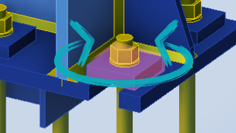
Bolt component model in IDEA StatiCa
What are bolts in IDEA StatiCa?
How are they modeled and how do they function?
Which problems can be solved with these bolts and which can not?
How do you model bolts in FEA?
Before we start to perform any experiments and to quote theoretical background, I want you to remember all the FEM models of connections, where you ever implemented bolted connections.
If you did this, of course. If not — it’s time for imagination.
What elements would you use for modelling a bolt? Beam elements? Solids? Or maybe even plates? (how?)
Would you apply any special FEM tools, like rigid bodies? Maybe nodes merging? Contact?
How to model washers, head and nut (or even nuts), and should you model them at all?
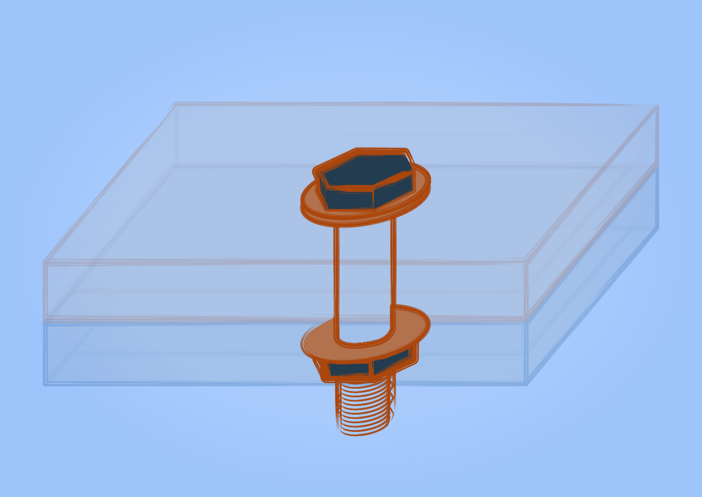
What does a bolt connection consist of?
Fragment of a bolted connection
Take a look on a picture and imagine the “ingredients” of a typical bolt connection.
Bolt
Bolt is the most intricate element here, naturally.
What exactly to model? Only the body? Nut(s)? Washers? Head? Some FEA models will even want to distinguish the thread from the bolt body.
The results of calculation varies depending on how you model the bolt and we will have closer look on options below.
Connected parts
Usually something 2-dimensional — two plates, incl. flange(s) or web(s) of some beam or column.
You can model them
Hole
What? How to model something that is nothing? But sometimes even the hole can be non-trivial problem, and not only the way how you model the contact between the bolt and hole edges, but even the diameter!
So, bolt, plates and the hole. What else? The way how all these parts contacting each other is also a part of the model. Contacts between plates, contacts between bolt and plates edges, even contacts between washers and plates — all of it can affect the behaviour of the model.
Typical bolt models in FEA
1. The simplest model
One-node model. Simple and impractical for connections
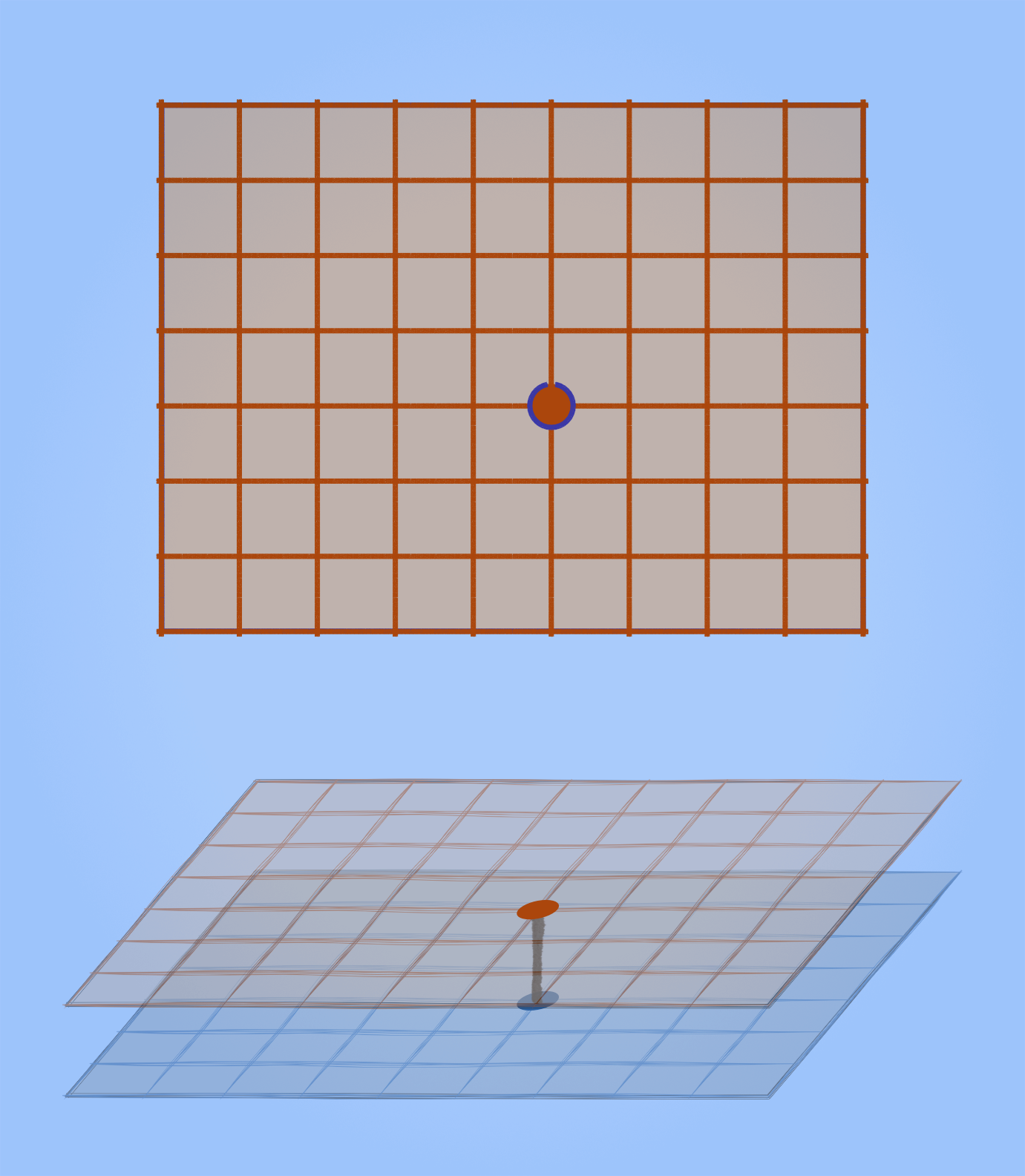
Two nodes on two plates, connected to each other. A rigid body element or displacements unification may be used. Or any other tools and element types that your FEM software provides.
This approach can do its job sometimes for some large models, like for riveted connection of two long plates, when you are not interested exactly in what exactly happens around the bolt or rivet.
There is no way to see the behaviour of the plate around the bolt, we will have knife effect and peak stresses. This is obviously too rough for connections calculation. We need to calculate the behaviour of material around the bolt, it is one the main goals of calculation.
2. Too complex models
Solid model. Too complicated to calculate
The other extreme. Models with solid bolt body, with solid head of the bolt. The complicated contacts including friction. Obviously, the plates in such models also being modelled as solids. Everything in 3D elements, everything in dynamics.
Cons are:
Too much calculation time
Too much nuances and fine tuning, not universal at all
Usually requires finite elements with mathematics of high complexity level
The results can not be code-checked. The spatial stresses are harder to analyze
3. Something in between. Lagom models
“Normal” engineering model of a bolt
Have a look at the picture. Looks like a balance between too simple and too complex approach, right?
We have here:
Plates as shell elements. Two-dimensional, easy to work with, easy to mesh, easy to read results. The hole is usually 8-noded, since this provides a good balance between results accuracy and mesh simplicity and effectiveness.
Bolt. The body between two plates. It can be 1-dimensional beam element or something a little bit more sophisticated.
Some media, connecting the bolt and edges of holes in plates.
Look at this as at a framework. We can adjust that body of the bolt. We can definitely adjust the interaction between elements, including third element.
We can also refine it a little, adding a contact between surfaces, modelling the nut-head-washer part a little bit more accurate etc. We can try different sizes of the hole and different number of its nodes.
And yes, finally, this is something that is implemented in IDEA StatiCa.
I’ve been netsurfing about this topic and with great pleasure discovered that one of my favourite FEA-authors, Łukasz Skotny, has recently published a series of relevant articles in his blog enterfea (not an ad), if you want to dive deeper in general questions of modelling bolts in FEA.
Bolts in IDEA StatiCa
Bolt
So, bolts in IDEA StatiCa are not solids?
No, they are not.
The body of a bolt is a special “spring”, the element that has different non-linear stiffness in different directions.
Shear
Shear displacement of the bolt component
The formula of the stiffness of the bolt component in the shear direction includes:
Bolt diameter and ultimate strength
Plates thickness and ultimate strength
I want to underline the second item on the list.
A bolt is more than a beam element; it considers both shearing and bearing. The same bolt will function with slightly different stiffness for S235 steel and S440.
The force from the bolt is transferred to the plate on only one side of the hole edge, where the bearing takes place. This is the result of non-linear media model between the bolt and the hole edge.
Bolts operate in a bi-linear manner. After reaching the plasticity point, the stiffness diagram becomes nearly horizontal. This enables bolts to redistribute shear forces among each other before reaching the limit state.
The “shear plane in thread” decreases the stiffness and the load-bearing capacity of the bolt.
Shear in Slotted holes
Shear displacement of the bolt component with a slotted hole
Bolts in slotted holes behave similarly, with one exception. The stiffness of such a connection in “long” direction is zero.
In “short” direction the bolt component itself has the same stiffness as usual bolt. But the bigger size of the hole will affect on the stress-strain state of the plate.
Can a bolt in this connection reach the end of a slotted hole?
Is it possible for the connection to deform for a couple centimeters and for the bolt to start transiting shear in the “long” direction of the hole?
In real life — yes, in IDEA StatiCa — no, impossible.
I believe that it is only possible if you perform dynamical analysis. So, maybe in IDEA DynamiCa… just kidding, it doesn’t exist. At least at the moment.
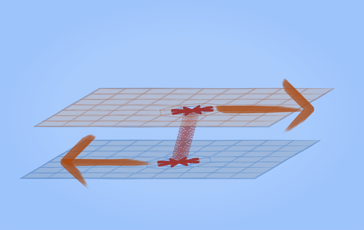
Shear in Friction bolts
Shear displacement of the bolt component
“You attached the same picture again”.
No, actually not. Take a closer look. The key difference here is how the force is transferred from one plate to another.
In this case the “spring” of the bolt component plays the role of friction force. Compared to shear bolt model, its stiffness is much higher.
The other important factor is that the media that fills the hole (the invisible element in the hole) behave differently. For these friction bolts the whole perimeter of the hole is involved, not only the bearing part. Naturally, because there is no bearing in friction connections.
Yes, here is no “real friction” from plate to plate. But could that even be possible or accurate for non-solid plates? I’m not sure, actually. In any case, the friction model of the bolt component demonstrates excellent results and been verified and calibrated on natural tests. So the simplicity and effectiveness, accuracy and resources economy.
Just a reminder, we have already been discussing this friction bolts earlier, do you remember? I shown some experiments of how forces in friction connection redistributes, and slightly described the difference between shear and friction bolts. Here is the link:
Tension
Tension deformation of the bolt component
Tension stiffness formulas includes parameters of not only the body of the bolt, but also its head, nut, washers. I believe this allows to minimize unnecessary elements in the model, saving computing time while maintaining accuracy.
Preloaded bolts
There is no actual pretension in IDEA StatiCa. From what I can observe the stiffness of the friction and shear bolts is the same. You may ask how this approach can be accurate at all and when I first discovered it I was also surprised.
But let’s figure this out. The limit tension force for any bolt is obviously higher than the pre-tension force and this means that by the time when limit state of the connection achieved, it would not matter if tensioned bolt was prestressed in the beginning or not — the force distribution between bolts should stay the same. You already use this approach in hand calculations, isn’t it?
And again, if you don’t believe in this approach, I’m going to recommend the verification examples. They may be found on official website (like this one), and recently a new book about verification of CBFEM approach was published.
Of course, the code-check is completely different for shear and friction bolts.
Hole
The hole used to be 8-noded opening. It is a tradition in bolt modelling in FEA, I believe. For example, the mentioned above articles of Łukasz Skotny also recommend using the 8 nodes.
But I’ve written “used to be”. And when I started to write this post, the version 24.0 was actual. But a week ago they released the 24.1, and now the holes are much more accurate!
Look at the pictures of these new meshes, they are really round and you can refine the mesh to achieve any accuracy:
New, more accurate meshing in IDEA StatiCa 24.1
Forces move from the bolt to the plates through the hole's edge. Shear force acts on just one side (the bearing side), while friction and tension affect the entire perimeter.
Contact between surfaces
Contact is a non-linear interaction of surfaces. A contact is created whenever bolts are inserted and surfaces are near enough to each other.
Bolts work for tension, contact — for compression. Bolts are never compressed, of course, even if they belong to compressed part of a connection.
It's important to keep it mind that surface contact does not implement friction. The only friction in IDEA StatiCa comes from the stiffness of a bolt component labeled as "friction bolt".
prying forces
Look at these two pictures of a simple end-plate connection of two CHS.
The bolt forces in the left picture are 12.5 kN, in the right — 18.4 kN.
What if I say you that applied force is 100 kN in both cases?
But how can 100 kN of external force summon nearly 150 kN of tension in the bolts in the right picture?
The answer is prying force
The deformation of plates create contact stresses between them and therefore the plate works like a lever and adds additional tension to bolts.
Here the thickness of plates is 20 mm and in the left picture above — 36 mm.
Rotation
This will not work. Bolt cannot withstand rotation around its axis. Even the preloaded one. But I believe that it is also not allowed by your structural code.
Why would I recommend to keep this in mind?
Plate washers
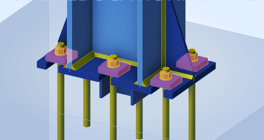
Rectangular plate washers modelled within the column base
Sometimes when modelling a column base or a similar joint with thick plate washers in IDEA StatiCa, you may want to include them in your design. This is a common desire and it can be modelled for sure. But there is a nuance.
Here is a column base on the picture. Shear key under the base plate allows us not to consider any shear forces on bolts and therefore plate washers (highlighted on the picture). So it is possible not to weld them to base plate, right?
But, “Analysis 0,0%”, nothing calculates. Why? Because it is statically unstable structure. Every plate washer can rotate around the bolt. Keep in mind — the bolt can not prevent rotation of the washer. And the contact under the washer is also only contact, not friction.
Even if nothing rotates the washer implicitly, the lack of fixation in this direction prevents the calculation.
The only way here to fix the statical instability is to weld a washer to base plate. Even one simple weld of minimal length and size is enough.
Bending of bolts
I’m really not sure of if this is a thing in IDEA StatiCa or not. I couldn't find any information on whether there is a mathematical representation for the bending of bolts in the bolt component model. However, while preparing this article, I did an interesting experiment that I want to share.
You have probably already seen such a picture — the symmetrical splice and you expect only shear forces in bolts, but plates starts to bend a little. Just a little, of course, the deformation on the picture is shown with a scale of x100.
Make it stand out
Whatever it is, the way you tell your story online can make all the difference.
The only explanation that I have is that only the bending of the bolt component can cause this bending of plates here, so this bending causes the contact stresses between plates and therefore a small tension in bolt component.
I may be wrong here, so please feel free to correct me, I'm open to being contacted!
In any case, do not expect the bolt to help you with problems that involves the real bending of a bolt.
You can try something like this to ensure that it will cause just only the error.
But don’t give up, solution is here below!
Pins
Beginning of version 24.0 IDEA StatiCa team released a new component — pin.
The original bolt is not meant to be a bent element, while the pin is designed specifically for that purpose.
The results include bending moment and shear force diagrams, stress check in pin and bearing check of all the plates.
Okay, this was huge I think.
Please let me know in comments section below if you have read the article from the beginning to the very end =)
I aimed to clarify all those questions that might hinder you in effective modelling of complex and interesting connections.
STILL HAVE QUESTIONS?
Torsion is not the most well-known topic about structural design. But there are a lot of interesting topics and a lot of possibilities to apply IDEA StatiCa.
If want to deepen your knowledge or want to get acquainted with the program, consider joining one of our comprehensive IDEA StatiCa courses.
Explore our courses to find the one that suits your needs best or request a custom course.
Get in touch with us today to learn more or to sign up!


